What is an OTDR?

OTDR, short for optical time-domain reflectometer, is an optoelectronic instrument used to characterize an optical fiber. It can be considered as the optical equivalent of an electronic time-domain reflectometer.
OTDR injects a series of optical pulses into the fiber under test. It also extracts, from the same end of the fiber,light that is scattered or reflected back from points along the fiber. The strength of the return pulses is measured and integrated as a function of time, and is plotted as a function of fiber length.
It may be used for estimating the fiber length and overall attenuation, including splice and mated-connector losses. It may also be used to locate faults, such as breaks, and to measure optical return loss. To measure the attenuation of multiple fibers, it is advisable to test from each end and then average the results, however this considerable extra work is contrary to the common claim that testing can be performed from only one end of the fiber.
In addition to required specialized optics and electronics, OTDRs have significant computing ability and a graphical display, so they may provide significant test automation. However, proper instrument operation and interpretation of an OTDR trace still requires special technical training and experience.
(Reference: FIBERSTORE OTDR Tutorial)
How Does an OTDR Work?
OTDR fiber tester works indirectly by using a unique phenomena of fiber to imply loss, unlike fiber optic light sources and power meters which measure the loss of the fiber optic cable plant directly by duplicating the transmitter and receiver of the fiber optic transmission links. It works like a radar. It first to send a signal for optical fiber, and then observe what return from one point to the information. This process will be repeated, then the results were averaged and to be displayed in the form of track, the track is described within the whole period of optical fiber (or the state) of the fiber on the strength of the signal.
As light travels along the fiber, a small proportion of it is lost by Rayleigh scattering. Rayleigh scattering is caused by the irregular scattering signal along the fiber produced. Given fiber optic transceiver parameters, the Rayleigh scattering power can be marked out. If the wavelength is known, it is proportional to the signal of pulse width, the longer backscattering, the stronger power. Rayleigh scattering power is related to the wavelength of emission signal, the shorter wavelength, the stronger power. That is to say, 1310nm signal path of the Rayleigh backscattering is higher than 1550 nm Rayleigh backscattering.
OTDR uses Rayleigh scattering to represent the characteristics of fiber optic. OTDR measurements back to part of scattering light to the OTDR port. As the light is scattered in all directions, some of it just happens to return back along the fiber towards the light source. This returned light is called backscatter as shown below.


The backscatter power is a fixed proportion of the incoming power and as the losses take their toll on the incoming power, the returned power also diminishes as shown in the figure.

OTDR uses the backscattered light to make its measurements. It sends out a very high power pulse and measures the light coming back. It can continuously measure the returned power level and hence deduce the losses encountered on the fiber.
Any additional losses such as connectors and fusion splices have the effect of suddenly reducing the transmitted power on the fiber and hence causing a corresponding change in backscatter power. The position and degree of the losses can be ascertained. At any point in time, the light the OTDR sees is the light scattered from the pulse passing through a region of the fiber.
Think of the OTDR pulse as being a virtual source that is testing all the fiber between itself and the OTDR as it moves down the fiber.Since it is possible to calibrate the speed of the pulse as it passes down the fiber, the OTDR can correlate what it sees in backscattered light with an actual location in the fiber. Thus it can create a display of the amount of backscattered light at any point in the fiber.
There are some calculations involved. Remember the light has to go out and come back, so you have to factor that into the time calculations, cutting the time in half and the loss calculations, since the light sees loss both ways. The power loss is a logarithmic function, so the power is measured in dB.
The amount of light scattered back to the OTDR is proportional to the backscatter of the fiber, peak power of the OTDR test pulse and the length of the pulse sent out. If you need more backscattered light to get good measurements, you can increase the pulse peak power or pulse width as shown in the picture.

Some events like connectors show a big pulse above the backscatter trace. That is a reflection from a connector, splice or the end of the fiber. They can be used to mark distances or even calculate the back reflection of connectors or splices, another parameter we want to test in single mode systems.
OTDRs are generally used for testing with a launch cable and may use a receive cable. The launch cable allows the OTDR to settle down after the test pulse is sent into the fiber and provides a reference connector for the first connector on the cable under test to determine its loss. A receive cable may be used on the far end to allow measurements of the connector on the end of the cable under test also.
FiberStore OTDRs are available with a variety of fiber types and wavelengths, including single mode fiber, multimode fiber, 1310nm, 1550nm, 1625nm, etc.. We also supply OTDRs of famous brands, such as JDSU MTS series, EXFO FTB series, YOKOGAWA AQ series and so on. OEM portable and handheld OTDRs (manufactured by FiberStore) are also available.Click for the OTDR price.
:: برچسبها:
optical time-domain reflectometer,OTDR fiber tester,OTDR price ,
:: بازدید از این مطلب : 1384
|
امتیاز مطلب : 135134
|
تعداد امتیازدهندگان : 30
|
مجموع امتیاز : 30


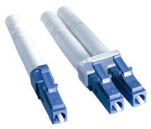 1. LC Connector
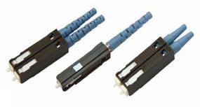 2. MU Connector
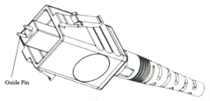
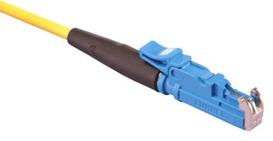 3. E2000 Connector
 4. MT-RJ Connector