|
|
|
نوشته شده توسط : sunprince
Introduction
Dense wavelength division multiplexing (DWDM)transmission systems, which have conventionally been adopted in long-haul backbone networks, are now being adopted in metropolitan area networks along with the recent rapid spread of multimedia services as typified by the Internet. In the applications for metropolitan area networks, the small form-factor pluggable (SFP) and other types of small optical transceivers are generally mounted in high density. Therefore, the development of DWDM optical transceivers in SFP package had been awaited.
Utilizing the accumulated technologies in SFP designing and wavelength control, the authors have successfully developed a 2.5Gbps optical transceiver for DWDM applications in the SFP platform (DWDM-SFP)by developing a compact coaxial transmitter optical subassembly (TOSA) with an integrated Peltier device.
Development of compact coaxial TOSA with integrated Peltier device
The external view of the newly developed coaxial TOSA with an integrated Peltier device and its pin assignments are shown in Fig. 1 and Fig. 2, respectively. A DFB laser diode (LD), a monitor photo diode (PD), a newly developed Peltier device for controlling the LD temperature and a thermistor for detecting the LD temperature are built into an 8-pin package. An isolator and a fiber receptacle are attached on it. By downsizing these internal parts and minimizing the heat load to reduce the power consumption, the authors realized a cooled coaxial TOSA that is 5.6 mm in diameter and 12.7 mm long, which is one-eighth the size of conventional cooled butterfly-type modules.
Figure 3 shows the case temperature dependence of he module’s power consumption. In this evaluation, he temperature and the current of the LD are set to 40 deg. C and 35 mA, respectively. As a result, the power consumption is successfully suppressed to 230 mW or lower, which is eight times smaller than the conventional butterfly-type module. This makes it easy to realize a DWDM-SFP having low power consumption and simple heat radiation structure.
Development of package
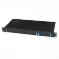
SFP is a pluggable optical transceiver of the size of little finger that is inserted into the open port of communication equipment as shown in Fig. 4. The outline dimensions and other important dimensional specifications of the SFP, such as the receptacle part that the optical connector is inserted into and the edge connector mating with the electrical connector of communication equipment, are standardized by a multi source agreement (MSA). The objective of the development was to create a package that meets not only MSA but also the following structure requirements at a low cost;1) the high-density packaging structure, 2) the efficient heat-radiating structure, and 3) the electromagnetic interference (EMI) shield structure. The solutions for satisfying these requirements are described below.
To realize the high-density packaging structure, the authors optimized the three-dimensional arrangement of the internal structure including the outline of the printed circuit board (PCB) and the electronic components on it.The maximum operating case temperatures of DWDM-SFP and TOSA are 70 and 75 deg. C, respectively. Therefore, it is necessary to keep the temperature difference between SFP and TOSA within 5 deg. C. The part number 1 and number 2 in Fig. 5 which take on the function of radiating heat, are made of copper alloy and their thermal conductivities are 350 and 300 W/mK, respectively. The part number 1 has the function of transporting heat from the transceiver IC
and other components mounted on the PCB to the rear of the SFP. The heat from TOSA and receiver optical sub-assembly (ROSA) is transported by the thermal sheets at the upper and bottom sides of the package. Figure 6 is a conceptual diagram showing these three heat conducting paths, and Fig. 7 shows the result of the thermal simulation. In Fig. 7, the temperature of the area“a” is low enough compared to that of the other areas, which indicates that TOSA is well separated thermally from other heat sources. Figure 8 is the measurement result of the case temperature difference between TOSA and SFP. It shows that the temperature difference is below 5 deg. C at any condition.3-3 EMI shield structure The typical method for creating an EMI shield structure is to give metal plating to the receptacle part. Because metal plating is costly, the authors developed a new structure for EMI shielding by three-dimensionally assembling the internal sheet metal parts instead of conducting the plating process to the receptacle part. Figure 9 shows the result of the EMI measurement of 16 pieces of DWDM-SFP. The Federal Communications Commission (FCC) specifies that the electromagnetic radiation is to be strictly limited to below 54 dBuV/m.
There are also have some development in circuit board and Wavelength control technique, here we just not describe in details.
Conclusion
The authors have successfully developed a SFP-sized 2.5Gbps optical transceiver for DWDM applications. Miniaturization and low power consumption (1 W) are achieved by developing the following approaches; a compact coaxial TOSA with an integrated Peltier device, an optimized heat-radiation structure, and a high-density mounting board with the newly developed transceiver IC. In addition, the optimized TOSA design and precise wavelength control by CPU have allowed the transceiver to have a good wavelength stability, which sufficiently meets the 100 GHz grid spacing with only the temperature control of direct modulated LD. Moreover, an excellent characteristic was achieved in long-haul transmission. The authors are planning to develop the DWDM-SFP having higher added values, such as further low power consumption and RoHS compliance, in future. If you want to know more professional knowledge about the SFP or DWDM/CWDM/OADM, please contact fiberstore. Here we will provide products such as CWDM/DWDM/modules, andCWDM OADM and DWDM OADM modules (such as DWDM 1 channel OADM).
:: بازدید از این مطلب : 801
|
امتیاز مطلب : 0
|
تعداد امتیازدهندگان : 0
|
مجموع امتیاز : 0
تاریخ انتشار : چهار شنبه 15 آذر 1391 |
نظرات ()
|
|
نوشته شده توسط : sunprince
The colored wire loom can be also described as colored split wire loom or know as colored convoluted tubing. It is a flexible polyurethane corrugated tube with a split down the side where you can insert your cable bundle, it is one of the most popular cable management products that can hold groups of wires together. Usually, the colored wire loom can be used in a wide range of applications, it can be used as cable protector and cable organizer at the same time, which means it can be used as your wiring convention and also protecting your wires and cables against abrasion and crushing. In speaking of the functions, the cable organizer is very efficient if there’s an instance where you have to add another wire subsequently, you can just easily slip it into the split wire loom without having to remove the whole cable or wire bundles. The colored wire loom that provided on FiberStore.com is a cinch to install, it is extremely durable and UV stable, the slit down the length of the tubing allows easy wire insertion yet basically remains closed during using and the corrugated design adds crush strength the loom as well as flexibility. There are now 100 meters Colored Wire loom/Convoluted Tubing PE-AD10-100M-FS/ PE-AD13-100M-FS/PE-AD15.8-100M-FS/PE-AD18.5-100M-FS/PE-AD21.2-100M-FS/PE-AD25-100M-FS/PE-AD28.5-50M-FS being provided on the website, welcome to visit it and choose what you want.
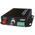
Then let's focus on the Optical time-domain reflectometer. The OTDR is a classic optoelectronic instrument used to characterize an optical fiber. In its testing work, it injects a series of optical pulses into the fiber, it could give you an overview of the whole system you test. It extracts, from the same end of the fiber, light that is scattered (Rayleigh backscatter) or reflected back from points along the fiber (This is equivalent to the way that an electronic time-domain reflectometer measures reflections caused by changes in the impedance of the cable under test). An OTDR may be used for estimating the fiber optic cable length and fiber optic cable overall attenuation, which including splice and mated-connector losses, and the OTDR can be also be used to locate faults, such as breaks, and to measure optical return loss. There are many types of OTDRs that designed for single mode troubleshooting, multi mode troubleshooting, both single mode & multi mode troubleshooting on the FiberStore.com website now, and the species nearly cover all the famous manufacturer of OTDR in the world. And for all the OTDR tester sale, we FiberStore.com provide one year warranty for each domestic and foreign brand product. Welcome to contact the FiberStore in case you have any problems or special requirement. We will try our best to provide you the best service.
:: بازدید از این مطلب : 791
|
امتیاز مطلب : 0
|
تعداد امتیازدهندگان : 0
|
مجموع امتیاز : 0
تاریخ انتشار : سه شنبه 14 آذر 1391 |
نظرات ()
|
|
نوشته شده توسط : sunprince
What is Multiplexing?
Multiplexing is the process of transmitting several different signals or information streams via a single carrier. The transmission of all these signals or streams takes place simultaneously by combining the several signals into one common signal that will efficiently moves through the carrier bandwidth. Once the signal reaches the destination point for one of the transmissions, that integrated signal re-assimilates into its original form and is received.
The exact configuration of the process depends a great deal on the mode or type of transmission. When dealing with an analog transmission, the signals are multiplexed using a process that is known as frequency-based multiplexing. This form, usually referred to as FDM, uses a process of dividing the bandwidth into a series of subchannels that will accommodate the transmissions and more or less allow them to flow forward in a parallel fashion.
A second common type is time-division multiplexing, or TDM. With TDM, the various signals or transmissions are carried over a common channel in much the same way as with FDM. The main difference is that the time-division approach allows for the signals to be transmitted in a series of alternating time slots. These alternating slots are still carried within a common channel, and still fit neatly into the available bandwidth.
Multiplexing is one of the common tools used today in just about every form of communications. A wide range of telephony services, including online applications, are able to function with such a high degree of efficiency because of the current technological advances this process has made possible. Optical networks also rely heavily on multiplexing to carry voice and video transmissions along concurrent but separate wavelengths from a point of origin to various points of determination. With an increasing range of communication functions taking place across the Internet, it has become an effective tool that aids in everything from videoconferences and web conferences to large data transmissions to even making a simple point-to-point telephone call.
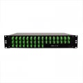
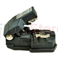
There are many kinds of the multiplexing, such as video multiplexing, data multiplexing, video/data multiplexing, frequency division multiplexing, voice/data multiplexing, optical multiplexing, etc. Everyone can choose what is suitable for him. What’s more, there are also many other fiber products that are very useful, like fiber cleaver(CT 30A fiber cleaver is recommended), fiber optic transceiver, fiber media converter, fiber patch cable, fiber optic tester(OTDR, optic power meter, PON power meter ), fiber cabling, CWDM and DWDM and so on. If you want more information, please contact to Fiberstore.
:: بازدید از این مطلب : 725
|
امتیاز مطلب : 0
|
تعداد امتیازدهندگان : 0
|
مجموع امتیاز : 0
تاریخ انتشار : دو شنبه 13 آذر 1391 |
نظرات ()
|
|
صفحه قبل 1 ... 7 8 9 10 11 ... 12 صفحه بعد
|
|
|