|
|
|
نوشته شده توسط : sunprince
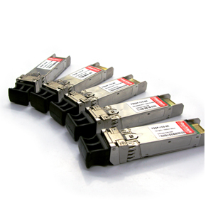
Several years ago, there was a report which said that the 10G/40G/100G optical transceivers would hit 1.44 billion dollars by 2014, driven by 10G SFP+ and tunable XFP modules. It is now 2014, and the forecasts have came true.
Infontetics Research released the report tracking 10-Gigabit (10G), 40-Gigabit (40G), and 100-Gigabit (100G) optical transceivers and transponders sold into the optical transport, carrier routing and switching, and enterprise markets.
In fact, the highlights of optical transceiver market have appeared years ago. Let's make a review.
- 10G, 40G, and 100G transceiver and transponder revenue was forecast by Infonetics Research to grow to 1.44 billion dollars worldwide by 2014, driven by SFP+ and tunable XFP technology, and by spikes in future 40G and 100G adoption.
- Tunable XFPs would be the major 10G growth opportunity for a long time, as they eliminated inventory management issues with fixed-wavelength modules, fulfilled the need for tunability as ROADM-based networking rises in popularity, and replaced the more-costly 300-PIN format.
- Meanwhile, SFP+ would replace XFP in the future, driven by strong growth in 850nm modules for 10-Gigabit Ethernet (10GbE) and 8/16G Fibre Channel (FC) applications.
- Shipments of next-generation 40G long-range (LR) and short-range (SR) optical transceivers would begin in 2010, primarily for enterprise and IP router applications.
 Revenue for 40G long-reach interfaces jumped 52 percent in 2009 over 2008, to 114.6 million dollars, while revenue for 40G 300-PIN short- and intermediate-reach interfaces dropped 35 percent, driven by price erosion and demand weakness. Revenue for 40G long-reach interfaces jumped 52 percent in 2009 over 2008, to 114.6 million dollars, while revenue for 40G 300-PIN short- and intermediate-reach interfaces dropped 35 percent, driven by price erosion and demand weakness.
- During the 2011-2012 timeframe, shipments of DQPSK transceivers were expected to outstrip those of DPSK, as the cost differential between the two drops. Worldwide revenue was forecast to grow nearly 10-fold from 2009 to 2014 for the tunable DQPSK 40G fiber transceiver.
Infonetics' report provided in-depth analysis, market size, and forecasts through 2014 frp manufacturer revenue and units shipped for 10G, 40G, and 100G transceivers and transponders. Specifically, the report tracked the following long- and short/intermediate-reach optical transceivers/transponders.
- 10G modules by tunable, WDM (fixed C-band), 1550nm,1310nm, and 850nm wavelengths, split by form-factor such as 300-PIN, SFP+, XFP, X2, XENPAK etc..
- 40G modules by tunable, 1310nm and 850nm wavelengths, split by form-factor such as DPSK, DQPSK, opto duo-binary (ODB) and other, 300-PIN SFI-5, 40GBASE-LR4, and 40GBSE-SR4.
- 100G modules by tunable, 1310nm and 850nm wavelengths, split by form-factor such as 100G DWDM, 100GBASE-LR4 (aka 4*25G non-return-to-zero, or NRZ), and 100GBASE-SR10 (aka 10*10G).
Nowadays, vendors providing products in the optical transceiver market include Cisco, Finisar, Avago, JDSU, and so on. Besides these famous companies, there are also many other manufacturers and suppliers who provide compatible transceivers with much more cheaper prices. For example, the compatible Finisar 10G SFP+ modules in FiberStore are all under 100 dollars!
:: برچسبها:
10G SFP+,40G fiber transceiver,Finisar 10G SFP+ ,
:: بازدید از این مطلب : 1518
|
امتیاز مطلب : 5
|
تعداد امتیازدهندگان : 1
|
مجموع امتیاز : 1
تاریخ انتشار : جمعه 9 اسفند 1392 |
نظرات ()
|
|
نوشته شده توسط : sunprince
Optical transceivers are classified by wavelengths, data rates, reaches, packaging types, electrical and optical interfaces, temperature ranges, etc. The mannfacturing followings a process from discrete optics to optical subassembly and integrated chips to module assembly and test. There are various optical transceivers currently used with optical access systems. Conventional transceiver technologies based on discrete optoelectronic chips, components, and coaxial packaging are still the key enabler for the industury. The high cost of transceivers is one of the major barriers to mass deployment.

PON transceivers are bidirectional devices that use different wavelengths to transmit and receive signals between an OLT at a central office (CO) and the ONTs at end users' premises. There are currently two standard types of transceivers: the diplexer and the triplexer transceivers, respectively. For the diplexer transceivers, the wavelengths are designed in accordance with industry standards, namely, 1310 nm for the upstream and 1490 nm for the downstream wavelengths. For triplexer transceivers, the 1550 nm wavelength is allocated for analog broadcast video overlay in the downstream direction. It is also possible that digital video signals are carried on the downstream 1490 nm wavelength using video over IP technologies.
For rapid adoption of FTTH, it is important to reduce the cost of optical transceivers. In particular, the overall PON system cost is weigthed more toward the ONU, as the OLT cost is shared among the number of FTTH users. So the ONU transceiver should be the main target for cost reduction whenever possible. In summary, the technological challenges in the optical transceivers for PON systems exist in the following areas:
1. High-output-optical-power and high-sensitivity OLT at the CO to compensate for the losses introduced by the optical splitter and the transmission fibers connecting subscribers' premises.
2. Burst-mode optical transmission technologies for the upstream link.
3. Cost-effective packaging of optical devices.
4. Integration of more digital and analog functions into a single IC.
PON transceivers still represent a very active area in industry research and development due to the huge market opportunity. Because of the PON point-to-multipoint nature, PON burst-mode transceiver must face several unique characteristics to meet the requirements. Despite widespread interest, there is still no related PON transceiver multisource agreement (MSA) defined to support this application. Optical module vendors normally collaborate with system vendors on a case-by-case basis in specifications for diverse systems. Because of the EPON influence, SFF and SFP MSAs gained some popularity, while other form factors like GBIC and proprietary triplexer designs still exist for this application.
From the EPON/G-PON system compatibility and reusability viewpoint, transceiver modules can be split into blocks of BOSA, electrical subassembly (ESA), housing, and thermal management. The BOSA module must satisfy transmitter optical power, and receiver sensitivity, etc. Considerations on the ESA side include burst-mode physical-media-dependant (PMD) drving performances, system control signal acceptable, high receiver sensitivity, and receiver circuits also need to be examined. One most important aspect is the specific testing items such as transmitter ON/OFF time and receiver settling time. It is of key importance for system designers to maintain system performance and utilize system data processing ability. On the mechanical side, many critical issues need to be considered, such as thermak, EMI, temperature, humidity effect, etc.
Besides the PON transceivers, the biggest Chinese transceiver modules manufacturer FiberStore also provides SFP port to RJ45 Netgear and Netgear SFP+ module such as 10GbASE-LR SFP+ module Netgear.
:: برچسبها:
optical transceivers,SFP port to RJ45 Netgear,10GbASE-LR SFP+ module Netgear ,
:: بازدید از این مطلب : 1276
|
امتیاز مطلب : 5
|
تعداد امتیازدهندگان : 1
|
مجموع امتیاز : 1
تاریخ انتشار : سه شنبه 6 اسفند 1392 |
نظرات ()
|
|
نوشته شده توسط : sunprince
What is an OTDR?

OTDR, short for optical time-domain reflectometer, is an optoelectronic instrument used to characterize an optical fiber. It can be considered as the optical equivalent of an electronic time-domain reflectometer.
OTDR injects a series of optical pulses into the fiber under test. It also extracts, from the same end of the fiber,light that is scattered or reflected back from points along the fiber. The strength of the return pulses is measured and integrated as a function of time, and is plotted as a function of fiber length.
It may be used for estimating the fiber length and overall attenuation, including splice and mated-connector losses. It may also be used to locate faults, such as breaks, and to measure optical return loss. To measure the attenuation of multiple fibers, it is advisable to test from each end and then average the results, however this considerable extra work is contrary to the common claim that testing can be performed from only one end of the fiber.
In addition to required specialized optics and electronics, OTDRs have significant computing ability and a graphical display, so they may provide significant test automation. However, proper instrument operation and interpretation of an OTDR trace still requires special technical training and experience.
(Reference: FIBERSTORE OTDR Tutorial)
How Does an OTDR Work?
OTDR fiber tester works indirectly by using a unique phenomena of fiber to imply loss, unlike fiber optic light sources and power meters which measure the loss of the fiber optic cable plant directly by duplicating the transmitter and receiver of the fiber optic transmission links. It works like a radar. It first to send a signal for optical fiber, and then observe what return from one point to the information. This process will be repeated, then the results were averaged and to be displayed in the form of track, the track is described within the whole period of optical fiber (or the state) of the fiber on the strength of the signal.
As light travels along the fiber, a small proportion of it is lost by Rayleigh scattering. Rayleigh scattering is caused by the irregular scattering signal along the fiber produced. Given fiber optic transceiver parameters, the Rayleigh scattering power can be marked out. If the wavelength is known, it is proportional to the signal of pulse width, the longer backscattering, the stronger power. Rayleigh scattering power is related to the wavelength of emission signal, the shorter wavelength, the stronger power. That is to say, 1310nm signal path of the Rayleigh backscattering is higher than 1550 nm Rayleigh backscattering.
OTDR uses Rayleigh scattering to represent the characteristics of fiber optic. OTDR measurements back to part of scattering light to the OTDR port. As the light is scattered in all directions, some of it just happens to return back along the fiber towards the light source. This returned light is called backscatter as shown below.
 
The backscatter power is a fixed proportion of the incoming power and as the losses take their toll on the incoming power, the returned power also diminishes as shown in the figure.

OTDR uses the backscattered light to make its measurements. It sends out a very high power pulse and measures the light coming back. It can continuously measure the returned power level and hence deduce the losses encountered on the fiber.
Any additional losses such as connectors and fusion splices have the effect of suddenly reducing the transmitted power on the fiber and hence causing a corresponding change in backscatter power. The position and degree of the losses can be ascertained. At any point in time, the light the OTDR sees is the light scattered from the pulse passing through a region of the fiber.
Think of the OTDR pulse as being a virtual source that is testing all the fiber between itself and the OTDR as it moves down the fiber.Since it is possible to calibrate the speed of the pulse as it passes down the fiber, the OTDR can correlate what it sees in backscattered light with an actual location in the fiber. Thus it can create a display of the amount of backscattered light at any point in the fiber.
There are some calculations involved. Remember the light has to go out and come back, so you have to factor that into the time calculations, cutting the time in half and the loss calculations, since the light sees loss both ways. The power loss is a logarithmic function, so the power is measured in dB.
The amount of light scattered back to the OTDR is proportional to the backscatter of the fiber, peak power of the OTDR test pulse and the length of the pulse sent out. If you need more backscattered light to get good measurements, you can increase the pulse peak power or pulse width as shown in the picture.

Some events like connectors show a big pulse above the backscatter trace. That is a reflection from a connector, splice or the end of the fiber. They can be used to mark distances or even calculate the back reflection of connectors or splices, another parameter we want to test in single mode systems.
OTDRs are generally used for testing with a launch cable and may use a receive cable. The launch cable allows the OTDR to settle down after the test pulse is sent into the fiber and provides a reference connector for the first connector on the cable under test to determine its loss. A receive cable may be used on the far end to allow measurements of the connector on the end of the cable under test also.
FiberStore OTDRs are available with a variety of fiber types and wavelengths, including single mode fiber, multimode fiber, 1310nm, 1550nm, 1625nm, etc.. We also supply OTDRs of famous brands, such as JDSU MTS series, EXFO FTB series, YOKOGAWA AQ series and so on. OEM portable and handheld OTDRs (manufactured by FiberStore) are also available.Click for the OTDR price.
:: برچسبها:
optical time-domain reflectometer,OTDR fiber tester,OTDR price ,
:: بازدید از این مطلب : 1172
|
امتیاز مطلب : 5
|
تعداد امتیازدهندگان : 1
|
مجموع امتیاز : 1
تاریخ انتشار : شنبه 5 بهمن 1392 |
نظرات ()
|
|
نوشته شده توسط : sunprince
Since the 1990s, many small form factor (SFF) fiber optic connectors have been developed to fill the interest in devices that may fit into tight spaces and permit denser packing of connections such as fiber patch cables. Some are miniaturized versions of older connectors, built around a 1.25mm ferrule rather than the 2.5mm ferrule used in ST, SC and FC connectors. Others are based on smaller versions of MT-type ferrule for multi fiber connections, or other brand new designs.
Most of these SFF connectors have a push-and-latch design that adapts easily to duplex connectors. LC, MU, E2000 and MT-RJ would be the most typical small form factor fiber optic connectors.
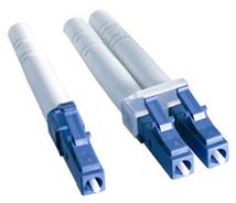 1. LC Connector 1. LC Connector
LC is short for Lucent Connector, licensed by Lucent. LC connector may also be called "Little Connector". It resembles a typical RJ45 telephone jack externally, while a miniature version of the SC connector internally. LC connector uses a 1.25mm ceramic (zirconia) ferrule instead of the 2.5mm ferrule and add a push-and-latch design providing pull-proof stability in system rack mounts. LC connectors are highly favored for single mode applications such as high-density connections, SFP transceivers, XFP transceivers, etc.. Generally, LC connectors can be found in simplex and duplex, single mode and multimode versions.
 2. MU Connector 2. MU Connector
MU is brief for Miniature Unit, produced by NTT. MU connector is known as "mini SC" and is popular in Japan. It has push-pull mechanism, utilizing a 1.25mm ferrule the same as LC connector. MU connectors' applications include high-speed data communications, voice networks, telecommunications, and dense wavelength division multiplexing (DWDM). They're also utilized in multiple optical connections so that as a self-retentive mechanism in backplane applications. MU connectors can be found in simplex and duplex versions.
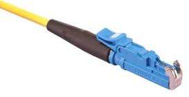 3. E2000 Connector 3. E2000 Connector
E2000, as known as laser shock hardening (LSH), is a technology generally used in Telecom, DWDM systems. E2000 connector is also called LX.5 connector. It looks like a miniature SC connector externally, like the MU connector utilizing a 1.25mm ferrule. You can easily install, with a snap-in and push-pull latching mechanism which clicks when fully inserted. E2000 connector includes a spring-loaded shutter which fully protects the ferrule from dust and scratches. The shutter closes automatically once the connector is disengaged, locking out impurities which could later result in network failure, and locking in possibly damaging lasers. When it's connected to the adapter the shutter opens automatically. E2000 connectors are available in single mode and multimode versions. FiberStore provides both E2000 to ST fiber patch cable and fibre optic patch cables E2000 LC rich in quality and best price.
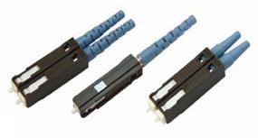
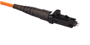 4. MT-RJ Connector 4. MT-RJ Connector
MT-RJ is short for Mechanical Transfer Registered Jack. MT-RJ connector's overall dimensions are comparable like a RJ45 connector. MT-RJ connector dose not make use of a 1.25mm ferrule, and it is design is derived from MT ferrule. It features a miniature two-fiber ferrule with two guide pins parallel to the fibers on the outside. The guides pins align ferrules precisely when mating two MT-RJ connectors. MT-RJ connectors are designed with male-female polarity which means male MT-RJ connector has two guide pins and feminine MT-RJ connector has two holes instead. MT-RJ connectors are utilized in intra building communication systems. Since they are designed as plugs and jacks, like RJ-45 telephone connectors, adapters can be used with a few designs, but are not required for all. MT-RJ connectors are available in duplex version only and multimode version only given that they use the two-fiber ferrules.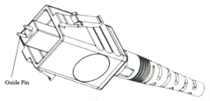
:: برچسبها:
SFF fiber optic connector,LC connector,MU connector,E2000 connector,MT-RJ connector ,
:: بازدید از این مطلب : 1866
|
امتیاز مطلب : 5
|
تعداد امتیازدهندگان : 1
|
مجموع امتیاز : 1
تاریخ انتشار : چهار شنبه 2 بهمن 1392 |
نظرات ()
|
|
نوشته شده توسط : sunprince

What is SFP+ Direct Attach Copper Cable?

SFP+ direct attach copper cable, also known as Twinax Cable, is a SFP+ cable assembly used in rack connections between servers and switches. It consists of a high speed copper cable and two copper SFP+ modules. The Plus SFP module allow hardware manufactures to achieve high port density, configurability and utilization at a very low cost and reduced power budget.
Direct Attach Cable assemblies are a high speed, cost-effective alternative to fiber optic cables in 10Gb Ethernet, 8Gb Fibre Channel and InfiniBand applications. They are suitable for short distances, making them ideal for highly cost-effective networking connectivity within a rack and between adjacent racks. They enable hardware OEMs and data center operators to achieve high port density and configurability at a low cost and reduced power requirement.
FiberStore SFP+ copper cable assemblies meet the industry MSA for signal integrity performance. The cables are hot-removable and hot-insertable: You can remove and replace them without powering off the switch or disrupting switch functions. A cable comprises a low-voltage cable assembly that connects directly into two SFP+ ports, one at each end of the cable. The cables use high-performance integrated duplex serial data links for bidirectional communication and are designed for data rates of up to 10 Gbps. Similar to the fiber patch cables, the SFP+ direct attach cables are made up of a cable and two connectors, with the difference that connectors are the SFP+ transceivers instead.
Types of SFP+ Direct Attach Copper Cables
SFP+ Copper Cable assemblies generally have two types which are Passive and Active versions.
 
1. SFP+ Passive Copper Cable
SFP+ passive copper cable assemblies offer high-speed connectivity between active equipment with SFP+ ports. The passive assemblies are compatible with hubs, switches, routers, servers, and network interface cards (NICs) from leading electronics manufacturers like Cisco, Juniper, etc..
2. SFP+ Active Copper Cable
SFP+ active copper cable assemblies contain low power circuitry in the connector to boost the signal and are driven from the port without additional power requirements. The active version provides a low cost alternative to optical transceivers, and are generally used for end of row or middle of row data center architectures for interconnect distances of up to 15 meters.
Applications of SFP+ Direct Attach Copper Cables
~ Networking – servers, routers and hubs
~ Enterprise storage
~ Telecommunication equipment
~ Network Interface Cards (NICs)
~ 10Gb Ethernet and Gigabit Ethernet (IEEE802.3ae)
~ Fibre Channel over Ethernet: 1, 2, 4 and 8G
~ InfiniBand standard SDR (2.5Gbps), DDR (5Gbps) and QDR (10Gbps)
~ Serial data transmission
~ High capacity I/O in Storage Area Networks, Network Attached Storage, and Storage Servers
~ Switched fabric I/O such as ultra high bandwidth switches and routers
~ Data center cabling infrastructure
~ High density connections between networking equipment
FiberStore SFP+ Direct Attach Copper Cables Solution
Our SFP+ twinax copper cables are avaliable with custom version and brand compatible version. All of them are 100% compatible with major brands like Cisco, HP, Juniper, Enterasys, Extreme, H3c and so on. If you want to order high quality compatible SFP+ cables and get worldwide delivery, we are your best choice.
For instance, our compatible Cisco SFP+ Copper Twinax direct-attach cables are suitable for very short distances and offer a cost-effective way to connect within racks and across adjacent racks. We can provide both passive Twinax cables in lengths of 1, 3 and 5 meters, and active Twinax cables in lengths of 7 and 10 meters. (Tips: The lengths can be customized up to the customers' requirements.)
Features of FiberStore SFP+ Direct Attach Copper Cables
~ 1m/3m/5m/7m/10m/12m available
~ RoHS Compatible
~ Enhanced EMI suppression
~ Low power consumption
~ Compatible to SFP+ MSA
~ Hot-pluggable SFP 20PIN footprint
~ Parallel pair cable
~ 24AWG through 30AWG cable available
~ Data rates backward compatible to 1Gbps
~ Support serial multi-gigabit data rates up to 10Gbps
~ Support for 1x, 2x, 4x and 8x Fibre Channel data rates
~ Low cost alternative to fiber optic cable assemblies
~ Pull-to-release retractable pin latch
~ I/O Connector designed for high speed differential signal applications
~ Temperature Range: 0~ 70°C
~ Passive and Active assemblies available (Active Version: Low Power Consumption: < 0.5W Power Supply: +3.3V)
FAQ of FiberStore SFP+ Direct Attach Copper Cables
1. What are the performance requirements for the cable assembly?
Our SFP+ copper passive and active cable assemblies meet the signal integrity requirements defined by the industry MSA SFF-8431. We can custom engineer cable assemblies to meet the requirements of a customer’s specific system architecture.
2. Are passive or active cable assemblies required?
Passive cables have no signal amplification in the assembly and rely on host system Electronic Dispersion Compensation (EDC) for signal amplification/equalization. Active cable assemblies have signal amplification and equalization built into the assembly. Active cable assemblies are typically used in host systems that do not employ EDC. This solution can be a cost savings to the customer.
3. What wire gauge is required?
We offer SFP+ cable assemblies in wire gauges to support customers' specific cable routing requirements. Smaller wire gauges results in reduced weight, improved airflow and a more flexible cable for ease of routing.
4. What cable lengths are required?
Cable length and wire gauge are related to the performance characteristics of the cable assembly. Longer cable lengths require heavier wire gauge, while shorter cable lengths can utilize a smaller gauge cable.
5. Are there any special customer requirements?
Examples of special customer requirements include: custom cable lengths, EEPROM programming, labeling and packaging, pull tab length and color, company logo, signal output de-emphasis, and signal output amplitude. We can custom engineer cables to specific customer system architecture.
:: برچسبها:
SFP module,fiber patch cables,Cisco SFP+ Copper Twinax ,
:: بازدید از این مطلب : 936
|
امتیاز مطلب : 5
|
تعداد امتیازدهندگان : 1
|
مجموع امتیاز : 1
تاریخ انتشار : دو شنبه 30 دی 1392 |
نظرات ()
|
|
نوشته شده توسط : sunprince
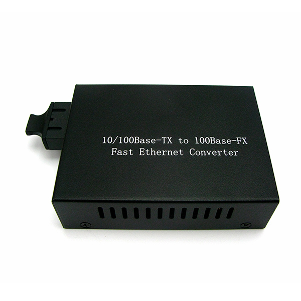
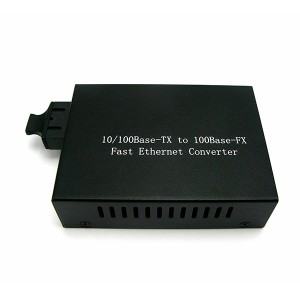
SFP Media Converter is a Fiber to Ethernet Media Converter with Fast Ethernet ports, dual-rate Fast/Gigabit Ethernet ports, or Gigabit Ethernet ports. The ports allow for flexible network configurations using SFP transceivers. And the Fast Ethernet SFP Media Converter uses Fast Ethernet SFPs.
According to the types of Fast Ethernet SFPs, there are corresponding kinds of Fast Ethernet SFP Media Converters. We should know the Fast Ethernet standards to understand this device.
Fast Ethernet is a collective term for a number of Ethernet standards that carry traffic at the nominal rate of 100Mbps, against the original Ethernet speed of 10Mbps. There are several Fast Ethernet standards including 100Base-T, 100Base-TX, 100Base-FX, 100Base-SX, 100Base-BX, etc.. Obviously, the "100" means 100Mbps rate.
100Base-T is an initial Fast Ethernet standard for twisted pair cables. The segment length for a 100Base-T cable is limited to 100m. 100Base-TX is the predominant form of Fast Ethernet, and runs over two wire-pairs inside a CAT5 or above cable. Since a typical CAT5 cable contains 4 pairs, it can support two 100Base-TX links with a wiring adaptor. Of the Fast Ethernet standards, 100Base-TX is by far the most widespread and is supported by the vast majority of Ethernet hardware currently produced.
100Base-FX is a version of Fast Ethernet over optical fiber. It uses a 1300nm NIR light wavelength transmitted via two strands of optical fiber, one for receive(RX) and the other for transmit(TX). 100Base-FX should use SC, ST, LC, MTRJ or MIC connectors with SC being the preferred option. However, it is not compatible with 10Base-FL, the 10Mbps version over optical fiber. A 100Base-FX SFP operates on ordinary MMF (multimode fiber) link spans up to 2km.
100Base-SX is another version of Fast Ethernet over optical fiber. It uses two strands of multimode optical fiber for RX and TX. It is a lower cost alternative to using 100Base-FX, because it uses short wavelength optics which are significantly less expensive than the long wavelength optics used in 100Base-FX. 100Base-SX can operate at distances up to 550m. It uses the same wavelength as 10Base-FL. Unlike 100Base-FX, this allows 100Base-SX to be backwards compatible with 10Base-FL. Because of the shorter wavelength used (850nm) and the shorter distance it can support, 100Base-SX uses less expensive optical components (LEDs instead of lasers) which make it an attractive option for those upgrading from 10Base-FL and those who do not require long distances.
100Base-BX is a version of Fast Ethernet over a single strand of optical fiber, while 100Base-FX uses a pair of fibers. Single-mode fiber is used along with a special multiplexer which splits the signal into TX and RX wavelengths. The two wavelengths used for TX and RX are 1310/1550nm. The terminals on each side of the fiber are not equal, as the one transmitting downstream uses the 1550nm wavelength, and the one transmitting upstream uses the 1310nm wavelength. Its transfer distances can be 10, 20 or 40 km. A 100Base-BX SFP operates on ordinary SMF (single mode fiber) single-strand link spans up to 10km.
Contraposing to these different standards, Fast Ethernet SFP Media Converters are designed with different SFP ports to support the 100Base-T SFP, 100Base-FX SFP, 100Base-SX SFP, 100Base-BX SFP and even 100Base-FX to 100Base-TX SFP transceiver which is used in the converter with two SFP ports (100Base-FX and 100Base-TX).
FiberStore supplies not only 100Base SFP Media Converters for Fast Ethernet, but also 1000Base SFP Media Converters for Gigabit Ethernet. These SFP Media Converters extend copper to fiber, multimode to multimode and multimode to single mode fiber by working with the SFP module. An extensive range of SFP Media Converters are in stock to meet every fiber conversion need.
Here are some features of FiberStore's Fast Ethernet SFP Media Converters
1. Extend Fast Ethernet network distances up to 120km
2. Support multimode and single mode fiber
3. Support SC, LC and ST fiber connectors
4. Special functions like Link Pass-Through, Far-End Fault, Auto-MDIX and Loopback
Tips: Link Pass Through is a troubleshooting feature that allows the media converter to monitor both the fiber and copper RX ports for loss of signal. Auto-MDIX is a function automatically detects and configures the twisted pair port on the converter to the correct MDI-X configuration.
:: برچسبها:
fiber to Ethernet media converter,100Base-FX to 100Base-TX SFP transceiver,SFP module ,
:: بازدید از این مطلب : 1400
|
امتیاز مطلب : 5
|
تعداد امتیازدهندگان : 1
|
مجموع امتیاز : 1
تاریخ انتشار : پنج شنبه 26 دی 1392 |
نظرات ()
|
|
نوشته شده توسط : sunprince
As we all know, SFP-OC48-LR2 is a type of Cisco SFP modules. But do you really know the meaning of the words in the SFP-OC48-LR2? I think the “SFP” and “LR2″ are known as SFP modules with 80km transfer distance by most people, while the “OC48″ is not understood by them including myself before today. And after searching on the internet, I write this article to talk about it.

In fact, many network engineers and IT managers are not up to speed on just what OC really means, although they have used the 2.5G SFP 80km or 1550 SFP 80km. And what all is available to enahnce their company’s applications within this bandwidth category. The first that we should know is, the OC is short for Optical Carrier (fiber optic based broadband network) with speed hierarchy starting with OC1 on optical facilities and going as follows.
OC1 = 51.840Mbps (the basic rate)
OC3 (3 times of OC1) = 155.52Mbps (about 155Mbps)
OC9 (9 times of OC1) = 466.56Mbps (not commonly used)
OC12 (12 times of OC1) = 622.08Mbps (about 622Mbps)
OC18 (18 times of OC1) = 933.12Mbps (not commonly used)
OC24 (24 times of OC1) = 1.244Gbps (not commonly used)
OC36 (36 times of OC1) = 1.866Gbps (not commonly used)
OC48 (48 times of OC-1s) = 2.488Gbps (about 2.5Gbps)
OC192 (192 times of OC1s) = 9.953Gbps (about 10Gbps)
OC48 is among the most used bandwidth that has applications including large enterprise or ISP backbone. Let’s discuss its specific advantages.
The utilisation of the internet by consumers and businesses is definitely an incredible market through which optical carriers are starting to supply the most leading edge appeal. With this particular facet of the internet world in your mind, any business or perhaps consumer should consider the incredible advantages offered in the OC48.
OC48 is used by larger businesses and corporations because they allow for an incredibly fast and dependable source of internet. They are currently equipped to handle probably the most amounts of data in the industry as well as offer the fastest speeds. As such, businesses that current operate on a much grander scale and would like to keep growing are the ones that help the most from this technique.
Within the optical carrier realm of data connection, there are quite a few ranges of speed and capability which are numerically labeled. The OC48 is really the mid-range source of data which allows to have an incredible fast rate of internet connection overall. It is probably the most popular carriers to replace T-Carrier lines. The T carriers of web connection for businesses was discovered and implemented in the 1960s for people who needed the fastest and more reliable data sources on the market for that time. This form of internet sourcing actually led the way for intranets and broad area networks that kept businesses connected all the time.
OC48 is really within the mid range of connection and strength. This range is complete with a processing capacity for 2.5Gbps which is actually quite robust. This really is perfect in strength for just about any larger business to expand within too. This optical carrier system could be quite expensive to establish for just about any business that often ranges in beginning costs of 30 to 40 thousand dollars. The monthly rates are quite steep as well yet many companies feel the costs are justified. As such, this is often from range for smaller to medium-sized businesses.
In order to operate an OC48 connection, there must be an amazing strong telecommunications source operating it. Some of the more reputable isps are beginning to come on line with this particular strength of the system. This, in turn, makes it more readily available for those that wish to use it.
:: برچسبها:
Cisco SFP modules,2 ,
5G SFP 80km,1550 SFP 80km ,
:: بازدید از این مطلب : 899
|
امتیاز مطلب : 5
|
تعداد امتیازدهندگان : 1
|
مجموع امتیاز : 1
تاریخ انتشار : سه شنبه 24 دی 1392 |
نظرات ()
|
|
نوشته شده توسط : sunprince
What is really a SFP transceiver?
SFP transceiver is a hot-pluggable fiber transceiver, of which the SFP stands for Small Form-factor Pluggable. The mechanical, electronic, and optical design and gratifaction derive from a Multi-source Agreement (MSA) within the fiber telecom industry. It is a pluggable form of SFF. SFP may be the interface between a network device mother board and a fiber optic or copper network cable.
Where is a SFP transceiver used?
SFP transceiver is able to support most of the fiber networking standards for example Gigabit Ethernet, Fiber Channel, SONET, along with a quantity of other communications standards. As a compact and hot-pluggable optical transceiver, it is utilized in optical communications for telecommunication and data communication applications. It connects a switch, router, or any other network devices to a fiber cabling plant. SFP transceivers can be found in Metro Access Network, Metro Core Network, Wide Area Networks (WANs), etc.
What types will the SFP transceiver have?
SFP transceiver has an immense variation available, each with different transmitters or receivers. This enables the user to configure and customize the transceiver to get the proper optical reach with either a multimode fiber (multi mode SFP) or single-mode fiber type.
The SFP module commonly is available in four categories which are SX (850nm), LX (1310nm), ZX (1550nm) and DWDM (DWDM wavelengths). All of them have an interface of a copper cable which permits a mother board to speak via UTP (unshielded twisted-pair) network cable. Click here for a good example of 1550 SFP 80km. There also exist a CWDM and single-mode bi-directional fiber optic cables which are 1310/1490nm upstream and downstream.
Tips: FYI, the industry has developed enhancements to the SFP MSA, known as SFP Plus (SFP+), that is designed for higher data rates, lower cost and better thermal performance. By using SFP+ transceivers, data rate at 10 Gbps could be achievable, including the 8 Gigabit Fiber Channel. When compared with XENPAK or XFP type of modules that have all of their circuitry inside, an SFP+ module leaves some of its circuitry to be implemented on the host board.
What benefits will the SFP transceiver have?
Firstly, SFP transceiver is pluggable that makes it easy to alter the optical interface in the last step of card manufacturing. It's also easy to accommodate different connector interfaces or a mix of SX and LX SFP.
Practically available, the SFP transceiver has the capability transfer rates as high as 4.25 Gbps. XFP, a form factor that is virtually identical to the SFP type, increases this amount by nearly three times, at 10 Gbps. The SFP transceiver is specified making compatible through the MSA between manufacturers, to ensure that different users who may use equipment from various manufacturers and providers can function effectively and smoothly without having to worry about errors and inconveniences.
Digital optical monitoring (DOM) or digital diagnostics monitoring (DDM) functions are based on the modern optical SFP transceiver according to the industry specifications of the SFF-8472 MSA. The consumer has the ability to constantly monitor real-time parameters of the SFP, for example optical input/outp power, supply voltage and laser bias current due to this feature.
A SFP cage is surface mounted to the PCB board to simply accept the transceiver. This not just provides easy replacement and reconfiguration, but additionally eliminates extra manufacturing steps and reduces cost. Because the optical component is taken away from soldering process, SFP transceivers have high optical reliability and permits the use of higher soldering temperatures.
SFP transceiver is a very popular format that's recommended by a large number of fiber optic component providers. These businesses carry SFP transceivers for those Cisco devices along with transceiver modules for many other manufacturers. So, if you want technology solutions for the networking applications, at this point you know what to consider. Here is a nice web store you can purchase Cisco SFP modules.
:: برچسبها:
multi mode SFP,1550 SFP 80km,LX SFP,Cisco SFP modules ,
:: بازدید از این مطلب : 824
|
امتیاز مطلب : 5
|
تعداد امتیازدهندگان : 1
|
مجموع امتیاز : 1
تاریخ انتشار : چهار شنبه 18 دی 1392 |
نظرات ()
|
|
نوشته شده توسط : sunprince
 The utilization of fiber optic cables for communication has opened up gates for communication multiplexing technologies that increase the capabilities at minimum costs. Coarse wavelength division multiplexing (CWDM) modulates different wavelength laser beams with multiple signals. Essentially, what this means is maximized utilization of a single fiber optic to deliver and get a large number of signals, minimizing costs for telecom companies. Companies simply employ the right optical amplifiers, multiplexers and demultiplexers to boost capacity from the fiber optic using CWDM technology. The utilization of fiber optic cables for communication has opened up gates for communication multiplexing technologies that increase the capabilities at minimum costs. Coarse wavelength division multiplexing (CWDM) modulates different wavelength laser beams with multiple signals. Essentially, what this means is maximized utilization of a single fiber optic to deliver and get a large number of signals, minimizing costs for telecom companies. Companies simply employ the right optical amplifiers, multiplexers and demultiplexers to boost capacity from the fiber optic using CWDM technology.
In CWDM technology, it comes with an increase in channel space. This means requirement of less sophisticated and less costly transceiver devices. Operating in the same window of 1550 nm and making use of OH-free silica fibers, maximum efficiencies are achieved in channels 31, 49, 51, 53, 55, 57, 59 and 61. The channels are spaced 20 nm apart. DWDM spaces them 0.4 nm apart. Less precision optics minimizing cost, uncooled lasers with lower maintenance requirements can therefore be used in CWDM devices, operating in the region of 1470, 1490, 1510, 1530, 1550, 1570, 1590 and 1660nm. 18 different channels can be used with wavelengths as much as 1270 nm. For instance, a 8 channel CWDM includes 8 different CWDM channels. In addition to being economical, power consumption for laser devices used in CWDM technology is also far less.
CWDM signals cannot be transmitted long term but are ideal for applications inside a range of 60 km for example in a city as well as for cable tv networks allowing upstream and downstream signals. CWDM product is usually considered a low-cost alternative which is now widely used to replace the DWDM system. Due to the benefit of CWDM technology uses low cost lasers that don't need cooling and low-cost passive filter. Moreover, if using CWDM technology, we can use low-cost and smaller transceivers such as CWDM 10Gig SFP+. However, because of relatively large CWDM channel spacing, so the system will reduce the number of available wavelengths, this also limits the system's transmission capacity.
Related technologies are dense wavelength division multiplexing (DWDM) and conventional WDM. Conventional WDM use the 3rd transmission window with a wavelength of 1550nm, accommodating as much as 8 channels. DWDM is identical however with a higher density channel. Systems could use 40 channels, each at 100 GHz spacing or 80 channels spaced 50 GHz apart. A technology, the ultra dense WDM is capable of doing working in a spacing of just 12.5 GHz, allowing more channels. However, DWDM and WDM are much more expensive in contrast to CWDM.
A quantity of manufacturers offer all related CWDM multiplexer, demultiplexer and optical amplifier. Networking solution providers would be the right individuals to seek guidance for use of CWDM, DWDM or WDM technology. They perform entire installation and commissioning from the right, integrated devices for error-free high speed, high data transmissions over fiber optic cables. Cost and gratifaction optimized CWDM solutions with built-in expansion capabilities can be found from reliable and trusted online network solution companies. Choose the best one with years of experience and technological expertise to provide the best CWDM solution and use the CWDM technology to construct your cost-effective fiber optic networks.
:: برچسبها:
CWDM technology,CWDM multiplexer,fiber optic network ,
:: بازدید از این مطلب : 931
|
امتیاز مطلب : 5
|
تعداد امتیازدهندگان : 1
|
مجموع امتیاز : 1
تاریخ انتشار : دو شنبه 16 دی 1392 |
نظرات ()
|
|
نوشته شده توسط : sunprince

What is an Optical Switch?
Optical Switch is a switch that enables signals in optical fibers or integrated optical circuits (IOCs) to be selectively switched from one circuit to another in telecommunication. Away from telecom, an optical switch is the unit that actually switches light between fibers, and a photonic switch is one that does this by exploiting nonlinear material properties to steer light (i.e., to switch wavelengths or signals within a given fiber).

An optical switch may operate by mechanical means, such as physically shifting an optical fiber to drive one or more alternative fibers, or by electro-optic effects, magneto-optic effects, or other methods. Slow optical switches, such as those using moving fibers, may be used for alternate routing of an optical switch transmission path, such as routing around a fault. Fast optical switches, such as those using electro-optic or magneto-optic effects, may be used to perform logic operations; also included in this category are semiconductor optical amplifiers, which are optoelectronic devices that can be used as optical switches and be integrated with discrete or integrated microelectronic circuits.
(Reference: WIKIPEDIA)
Optical Switching Technology
Optical switching technology as an important foundation for all-optical communication network technology, its development and application will greatly affect the development direction of future optical communication networks. So, how does it work?
Optical signals are multiplexed in three ways, space division, time division, and WDM. The corresponding optical switching methods space division switching, time division switching and wave division switching to complete the three multiplexed channels.
Space Division SwitchingIt is the domain swap space on the optical signal, the basic functional components of the spatial light switch. Spatial light switch is the principle of optical switching components gate array switch can be in any of the multiple input multiple output fiber established path. It can constitute an empty spectroscopic switching unit, and other types of switches can also together constitute a time-division switching unit or wave stars. Empty spectral switches generally have both fiber-based and space-based space division switching is a division of swap space.
Time Division SwitchingThis multiplexed signal multiplexing method is a communication network, a channel is divided into a number of different time slots, each optical path signal distribution occupy different time slots, a baseband channel to fit the high-speed optical data stream transmission. Need to use time division switching time slot interchange. The time slot interchanger of the input signal is sequentially written to the optical buffer, and then read out in accordance with established order, thus achieving a one frame at any one time slot exchange to another time slot and outputs completed the timing exchange program. Usually bistable lasers can be used as an optical buffer, but it is only the bit output, and can not meet the demand of high-speed switching and large capacity. While the optical fiber delay line is a more time-division switching device, the time-division-multiplexed signal light input to the optical splitter, so that each of its output channels are only a light signal of the same timeslot, then these signals combined through different optical delay line, after a signal of the type of delay line to obtain a different time delay, the final combination fits before the signals are multiplexed with the original signal, thereby completing a time-division switching.
Wave Division SwitchingShips in WDM systems, the source and destination are required to transmit signals using the same wavelength, such as non-multiplexed so multiplexed in wavelength division multiplexing technology is widely used in the optical transmission system, each multiplex terminal using additional multiplexers, thus increasing system cost and complexity. In the WDM system, wave spectral exchange in the intermediate transmission nodes, to meet no additional devices to achieve wavelength division multiplexing system source and destination communicate with each other, and you can save system resources, improve resource utilization rate. Wave spectroscopic switching system first lightwave signal demultiplexer is divided into plural wave splitting is required to exchange the wavelength channels in each channel wavelength switching the last signal obtained after multiplexing composed of a dense wave division multiplexing signal from an optical output, which take advantage of the characteristics of the fiber-optic broadband, low-loss band multiplexing multiple optical signals, greatly improving the utilization of the Fiber Channel, to improve the communication system capacity.
There are also hybrid switching technologies which are used in large-scale communication network in a variety of the optical path switching technology a mixture of multi-level link connection. In large-scale networks need to be multi-channel signal splitter and then access different link, making the advantages of wavelength division multiplexing can not play, so using wavelength division multiplexing technology levels connecting link, and then space division switching technology used in all levels of link exchange to complete the interface between the link, finally destination and then wave of the exchange of technical output corresponding optical signals, signal combined final sub output. Mixed-use switching technology time mixed, air separation - after midnight - wavelength division mixed several minutes - hours of mixing, air separation - wavelength division.
All-Optical Network Switching Technology
To realize the all optical network switching, the first is to use the circuit switch based optical add-drop multiplexing (OADM) and OXC (optical cross connect) technology to achieve wavelength switching, and then further realization of optical packed switching.
Wavelength switching is based on wavelength in units of optical circuit switched domain, wavelength switching optical signals to provide end-to-end routing and wavelength assignment channel. Wavelength switching key is to use the corresponding network node equipment, optical add-drop multiplexing optical cross-connect. Optical add-drop multiplexing the working principle is based on all-optical network nodes drop and insert the required wavelength path. Its main constituent elements of the multiplexer reconciliation multiplexer, as well as optical switches and tunable harmonic, etc.. Optical add-drop multiplexing of the working principle and the synchronous digital hierarchy (SDH) multiplexer separate interpolation function is similar, but in the time domain, while the other is acting in the optical domain. The optical cross-connect and the synchronous digital system digital cross-connect (DXC) similar effect, but to achieve the cross-connection to the passage in the wavelength at which the optical network node.
Optical wavelength to exchange essentially took office contingent is not efficient optical switching, connection-oriented attribute it established wavelength channel re-distribution to achieve maximum utilization efficiency can not be achieved, even if the communication is idle. Optical packet switching can be implemented with a minimum switching granularity multiplexing of bandwidth resources, improve the communication efficiency of the optical network. Optical packet switching is generally light and transparent packet-switched (OTPS), optical burst switching (OBS) and optical label switching (OMPLS). The optical the transparent packet switching characteristics is the packet length is fixed, the use of synchronous switching manner, the need for all input packets are synchronized in time, thus increasing the technical difficulty and increase the use of cost. The transmission optical burst the use of a variable-length packet data transfer header control information and separated in time and space, to overcome the shortcomings of the synchronization time, but it is possible to generate the packet loss problem. Optical label switching is carried out to add a tag in the IP packet in the core network access re-packet, and the routing method according to the tag inside the core network.
Although optical switching communication occasion require a higher (generally more than 10Gbps) is more suitable for lower transmission costs and greater system capacity can be achieved; via digital transmission rate when the system requirements require a lower transmission rate (2.5Gbps or less), the connection configuration more flexible access may be more appropriate to use the old-fashioned way of photoelectric conversion. Therefore, the practical application of the current should be selected according to the application scenarios appropriate system deployment.
With the future communication network technology development and all-optical network, optical switching technology will be more innovative and more efficient ways for communication network photochemical contribute to become an important part of social development and people's lives.
Types of Optical Switches
Optical switches can be divided into mechanical and non-mechanical ones according to the driving methods.
Mechanical optical switch relies on the movement of optical fiber or optical elements to convert the optical path, such as a mobile optical fiber type, moving the sleeve to move the lens (including mirrors, prisms and self-focusing lens) types. The biggest advantage of this kind of optical switch is a low insertion loss and low crosstalk. Its disadvantage is slow and easy to wear, easy to vibration, impact shocks.
Non-mechanical optical switch relies electro-optic, magneto-optic, thermo-optic and other effects to change the refractive index of the optical waveguide, the optical path changes, such as electro-optic switch, magneto-optic switch, and thermo-optic switch. This kind of optical switch has good repeatability, fast switching speed, high reliability, long life and other advantages, and small size, can be monolithically integrated. The disadvantage is that the insertion loss and crosstalk performance is not ideal, which should be improved.
Here are three common optical switches.
Opto-Mechanical Switch
Opto-mechanical switch is the oldest type of optical switch and the most widely deployed at the time. These devices achieve switching by moving fiber or other bulk optic elements by means of stepper motors or relay arms. This causes them to be relatively slow with switching times in the 10-100 ms range. They can achieve excellent reliability, insertion loss, and crosstalk. Usually, opto-mechanical optical switches collimate the optical beam from each input and output fiber and move these collimated beams around inside the device. This allows for low optical loss, and allows distance between the input and output fiber without deleterious effects. These devices have more bulk compared to other alternatives, although new micro-mechanical devices overcome this.
Thermo-Optic Switch
Thermo-optic switches are normally based on waveguides made in polymers or silica. For operation, they rely on the change of refractive index with temperature created by a resistive heater placed above the waveguide. Their slowness does not limit them in current applications.
Electro-Optic Switch
These are typically semiconductor-based, and their operation depends on the change of refractive index with electric field. This characteristic makes them intrinsically high-speed devices with low power consumption. However, neither the electro-optic nor thermo-optic optical switches can yet match the insertion loss, backreflection, and long-term stability of opto-mechanical optical switches. The latest technology incorporates all-optical switches that can cross-connect fibers without translating the signal into the electrical domain. This greatly increases switching speed, allowing today's telcos and networks to increase data rates. However, this technology is only now in development, and deployed systems cost much more than systems that use traditional opto-mechanical switches.
Optical Switch Protection System for DWDM Network Security
Optical switch protection system for the security of communication network provides a set of economic, practical solutions, the formation of a non-blocking, high reliability, flexible, anti-disaster ability of the optical communication network. Optical switch protection system by the automatic switching and network management stations, you can achieve light switch protection, monitoring and the optical path of the optical power emergency dispatch three main functions.
DWDM system in the trunk and local fiber optic transmission network has a large number of applications. Due to the amount of traffic carried by focus on the importance of safety more and more attention in the event of full resistance will affect all business network hosted. The DWDM network security has always been the most important in the transmission maintenance work. However, DWDM protection technology by its own limitations, has problems such as not flexible, large investment, and the effect is not ideal. Then the optical switch protection technology comes to play a very important role in the DWDM network security.
The optical switch protection system switching control module is a set of optical switches, optical power monitoring, stable light source monitoring in one of the high level of integration modules. Optical power monitoring module and optical switch control module coordination, selection of splitting ratio of 97:3 is more appropriate on the trunk, the equivalent of approximately 0.2dB attenuation on the transmission line; optical switching module contains 1x2 or 2x2 optical switch, controlled by the switch between the main and backup light routing operation.
Real-time monitoring of the optical power monitoring module communication optical fiber optical power value reported to the main control module; analysis and comparison of the main control module, found that the change in value of the optical power exceeds a preset threshold switching immediately issued instructions to the optical switch module; optical switch module by the Directive instantly switching action has occurred. In order to achieve a switching operation.
The optical path automatically switch protective equipment involved in trunk transmission system did not affect the transmission characteristics. In fact, switching equipment involved in the optical switch and splitter only two passive optical devices.
One end of the switching unit is connected to the transceiver of the transmission system, the main fiber optic cable and the spare cable, respectively connected to two output terminals of the 2x2 optical switch. When the optical path occurs when the optical power is abnormal, the optical switch is automatically switched to the alternate route.
It is understood that the optical switch protection system has the following advantages. Fast switching speed, the optical switch switching speed ships 5ms, plus system analysis, the response time of a single-ended switching time of less than 20ms, the switching time of less than 50ms for the entire system, the basic switching operation can be done without interrupting the communication, to achieve business grade level of protection.
Switching, high reliability, implemented through the optical power monitoring, to avoid false alarm of the optical frame, ensure switched judgment is correct. The spare fiber routing monitoring, to ensure the validity of the switch, and continue to be monitored after switching optical path.
Emergency dispatch function, simply switching command issued from the program, you can deploy routing to facilitate the realization of the non-blocking cutover and line maintenance work. The switch device for a transmission system is transparent, i.e. the switching device does not require the type of transmission system can use either SDH or DWDM.
The optical switch protection DWDM is an economical and safe a line protection method, but the the light automatic protection system intervention to DWDM systems, there are many issues to consider. Splitter 97:3 spectral, optical switching device insertion loss is about 2 dB intervention light switching device, the system has an additional two-fiber jumper whose fiber insertion loss is estimated as 1 dB, so the whole switching device Interventional theoretically maximum will bring 3dB attenuation, and many cases of practical use only in 1.5-2.5dB.
Optical automatic switching system for the DWDM line protection is both safe and economical means of protection. The future, as the size of the network continues to expand, optical switch protection systems will play a more important role to meet the requirements of the assessment indicators, to improve the safety of operation of the transmission network.
FiberStore's Optical Switch Solution
FiberStore's optical switches are based on Opto-Mechanical technology with proven reliability and available as optical switch 1x1, 1x2, 2x2 Non-Latching, Latching, Single-mode, Multimode versions. Besides these high performance Opto-Mechanical switch solutions, if you want to buy the other types such as thermo-optic and electro-optic ones, please contact the sales for special Custom Service.
Available Configuration
1X1 Mechanical 1X2 Mechanical
1X4 Mechanical 1X8 Mechanical
1X16 Mechanical 2X2 Mechanical
2X2B Mechanical 2X2BA Mechanical
D1X2 Mechanical D2X2 Mechanical
D2X2B Mechanical
Available Mode
Single-mode
Multimode
Available Control Model
Latching
Non-lantching
:: برچسبها:
optical switch,optical switches,optical switch 1x1 ,
:: بازدید از این مطلب : 1578
|
امتیاز مطلب : 5
|
تعداد امتیازدهندگان : 1
|
مجموع امتیاز : 1
تاریخ انتشار : جمعه 13 دی 1392 |
نظرات ()
|
|
صفحه قبل 2 3 4 5 ... 12 صفحه بعد
|
|
|